
News
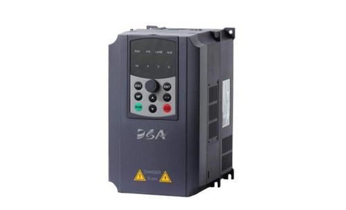
13 common parameters of frequency converter
Since the normal operation of the inverter depends on the reasonable setting of various parameters (all within a specific range), any single parameter configuration error may cause a malfunction, so the relevant parameters must be set accurately.
1. Control method
That is, speed control, torque control, PID control or other methods. After adopting the control method, static or dynamic identification is generally required according to the control accuracy.
2. Minimum operating frequency
The motor has poor heat dissipation when running at the lowest speed, and long-term low-speed operation will cause the motor to burn out. In addition, the cable current increases at low speed, which may cause cable overheating.
3. Maximum operating frequency
The maximum frequency of the inverter is usually 60Hz, and some models can reach 400Hz. High-frequency drive will cause the motor to run at overspeed, but the bearing design of ordinary motors does not support long-term over-rated speed operation. At the same time, the centrifugal force generated by high-speed rotation may exceed the bearing limit of the rotor structure.
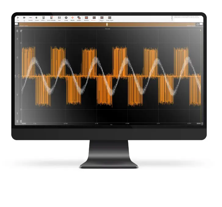
4. Carrier frequency
The increase in carrier frequency will intensify the high-frequency harmonic components, which in turn is closely related to the cable length, motor temperature rise, cable heating and inverter heat dissipation performance.
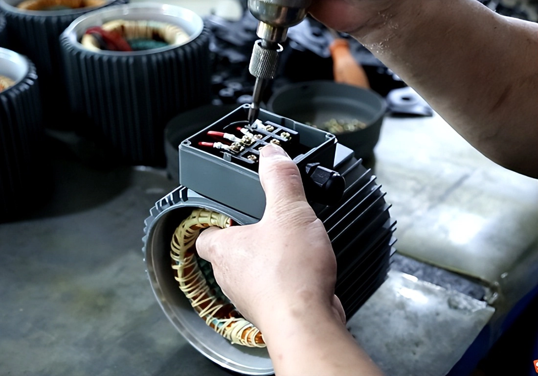
5. Motor parameters
When setting the inverter parameters, key parameters such as motor power, current, voltage, speed and maximum frequency can be directly read and entered from the motor nameplate.
6. Frequency Hopping
During operation, certain frequencies may cause resonance, especially in the case of taller equipment; when adjusting the compressor, its natural vibration frequency must be avoided.
7. Acceleration and deceleration time
The inverter’s acceleration time and deceleration time correspond to the rise and fall of the output frequency. This time parameter is usually determined by the slope of the frequency command. To avoid overcurrent during motor acceleration or overvoltage during deceleration, the rise/fall rate of the frequency command must be set reasonably.
The acceleration time setting needs to ensure that the acceleration current does not exceed the overcurrent capacity of the inverter to avoid tripping due to overcurrent; the deceleration time setting needs to prevent the smoothing circuit voltage from being too high to avoid shutdown caused by regeneration overvoltage. The acceleration and deceleration time can be determined based on load calculation, but the empirical method is usually used in actual debugging: first set a longer acceleration and deceleration time based on the load characteristics, and observe whether an alarm occurs by starting and stopping; then gradually shorten the set value, with the principle of no alarm during operation, and determine the optimal parameters after multiple verifications.
8. Torque boost
Also called torque compensation, it is a method of increasing the low frequency range f/V to compensate for the torque reduction at low speed caused by the stator winding resistance of the motor. When set to automatic, the voltage during acceleration can be automatically increased to compensate for the starting torque, so that the motor can accelerate smoothly. If manual compensation is used, the best curve can be selected through experiments based on the load characteristics, especially the starting characteristics of the load. For variable torque loads, if the selection is inappropriate, the output voltage at low speed will be too high, which will waste electric energy, and even the current will be large when the motor starts with load, and the speed will not increase.
9. Electronic thermal overload protection
This function is used to prevent the motor from overheating. The built-in CPU of the inverter will calculate the motor temperature rise in real time according to the operating current and frequency, thereby realizing overheat protection. This function is only applicable to “one-to-one” occasions; if it is a “one-to-many” configuration, a thermal relay must be installed separately on each motor. Electronic thermal protection setting value (%) = [motor rated current (A) / inverter rated output current (A)] × 100%.
10. Bias frequency
Sometimes it is also called deviation frequency or frequency deviation setting. Its purpose is that when the frequency is set by an external analog signal (voltage or current), this function can be used to adjust the output frequency when the frequency setting signal is the lowest. For some inverters, when the frequency setting signal is 0%, the deviation value can be applied in the range of 0 ~ fmax. Some inverters (such as Meidensha and Sanken) can also set the bias polarity. For example, when the frequency setting signal is 0% during debugging, the inverter output frequency is not 0Hz, but xHz. At this time, setting the bias frequency to negative xHz can make the inverter output frequency 0Hz.
11. Frequency setting signal gain
This function is only valid when the frequency is set by an external analog signal. It is used to compensate for the inconsistency between the external setting signal voltage and the voltage (+10v) inside the inverter; it also facilitates the selection of the analog setting signal voltage. When setting, when the analog input signal is the maximum (such as 10v, 5v or 20mA), find the frequency percentage of the output f/V graph and set it as a parameter; if the external setting signal is 0~5v, if the inverter output frequency is 0~50Hz, then set the gain signal to 200%.
12. Frequency Limit
The frequency limit function is used to set the upper and lower limits of the inverter output frequency to prevent the output frequency from being too high or too low due to misoperation or failure of the external frequency setting signal source, thereby protecting the safety of the equipment. Users can flexibly set it according to actual application requirements. In addition, this function can also be used for speed limitation. For example, in light-load occasions such as belt conveyors, the upper limit frequency of the inverter can be set to make the equipment run at a lower and constant speed, reducing the wear of the machinery and belts.
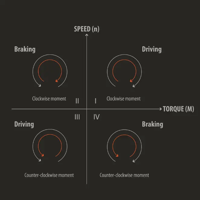
13. Torque limit
The torque limit function is divided into two categories: drive torque limit and brake torque limit. This function is based on the output voltage and current value of the inverter. The CPU calculates the torque in real time, which can significantly improve the impact load recovery characteristics of the equipment during acceleration, deceleration and constant speed operation. The torque limit function can realize automatic acceleration and deceleration control. When the acceleration and deceleration time is less than the load inertia time, it can still ensure that the motor automatically completes the acceleration and deceleration process according to the set torque value.
The drive torque function provides a strong starting torque. In steady-state operation, the torque function will control the motor slip and limit the motor torque to the maximum setting value. When the load torque suddenly increases, even when the acceleration time is set too short, it will not cause the inverter to trip. When the acceleration time is set too short, the motor torque will not exceed the maximum setting value. A large drive torque is beneficial to starting, and it is more appropriate to set it to 80 ~ 100%.
The smaller the braking torque setting value, the greater the braking force, which is suitable for fast acceleration and deceleration occasions. If the braking torque setting value is too large, an overvoltage alarm will be triggered. When the braking torque is set to 0%, the main capacitor feedback energy can approach zero, so that no braking resistor is required during deceleration and no tripping can be achieved. However, it should be noted that some loads may experience short-term idling during deceleration when the braking torque is set to 0%, resulting in repeated start and stop of the inverter and severe current fluctuations, which may cause the equipment to trip in severe cases.