News
Basic hydraulic circuits
The so-called basic hydraulic circuits are typical circuits composed of related hydraulic components to complete certain specific functions. Although the hydraulic systems of some hydraulic equipment are very complex, they are usually composed of some basic circuits. Therefore, mastering the composition, principles and characteristics of some basic circuits will help to understand and analyze a complete hydraulic system.
Pressure control circuit
The pressure control circuit is a circuit that uses a pressure control valve to control the pressure of the whole or a part of the system to meet the force or torque requirements of the hydraulic actuator. This type of circuit includes pressure regulation and reduction, pressure increase, pressure maintenance, unloading, and balance.
Pressure regulating circuit:
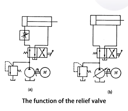
The function of the pressure regulating circuit is to keep the pressure of the whole or part of the hydraulic system constant or not exceeding a certain value. In a fixed displacement pump system, the oil supply pressure of the hydraulic pump can be adjusted by a relief valve. In a variable displacement pump system, a safety valve is used to limit the maximum pressure of the system and prevent it from overloading. If more than two pressures are required in the system, a multi-stage pressure regulating circuit can be used.
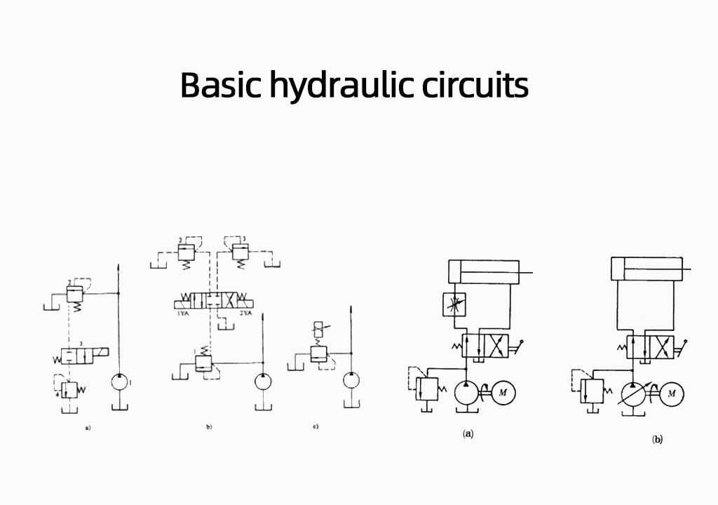
Pressure control circuit 1. Single-stage pressure regulating circuit as shown in the figure below, a parallel overflow valve 2 is set at the outlet of the hydraulic pump to form a single-stage pressure regulating circuit, thereby controlling the working pressure of the hydraulic
Pressure control circuit
2. Two-stage pressure regulation circuit
3. Multi-stage pressure regulation circuit
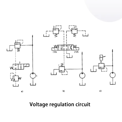
4. Continuous and proportional pressure regulation circuit
The “a” shown in the above figure is a two-stage pressure control circuit, which can realize two different system pressure control. By the relief valve 2 and relief valve 4 each regulating a level, when the two-position two-way solenoid valve 3 is in the position shown in the figure, the system pressure is regulated by the valve 2, when the valve 3 is powered in the right position, the system pressure is regulated by the valve 4, but be careful: the valve 4 regulating pressure must be less than the valve 2 regulating pressure, otherwise it cannot be realized; when the system pressure is regulated by the valve 4, the pilot valve port of the relief valve 2 is closed, but the main valve is opened, the hydraulic pump relief flow through the main valve back to the tank. As shown in the figure above, “b” shown by the relief valve 1, 2, 3, respectively, to control the pressure of the system, thus forming a three-stage pressure regulating circuit. When the two solenoids are not charged, the system pressure is regulated by the valve 1, when the 1YA is charged, by the valve 2 regulating the system pressure; when the 2YA is charged when the system pressure is regulated by the valve 3. However, in this pressure regulating circuit, valve 2 and valve 3 regulating pressure are less than the valve 1 regulating pressure, and valve 2 and valve 3 regulating pressure between what is not a certain relationship
As shown in the above figure “c” adjust the pilot type proportional solenoid relief valve input current I, you can realize the system pressure stepless adjustment, so not only the circuit structure is simple, but the pressure switching is also smooth. And easier to make the system to achieve remote control or program control.
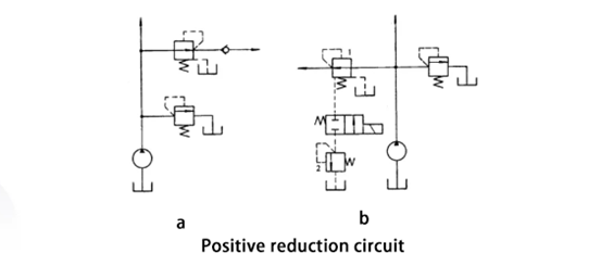
Pressure Reducing Circuit: The function of the pressure-reducing circuit is to stabilize a portion of the system at a lower pressure than the system pressure. The most common pressure-reducing circuits are connected to the main line using a fixed-value pressure-reducing valve, as shown in “a” in the figure below. Check the valve in the circuit for the main oil circuit pressure reduction (lower than the pressure reducing valve adjustment pressure) to prevent backflow of oil, the short-term pressure preservation, pressure reducing circuit can also be used similar to two-stage or multi-stage pressure regulation method to obtain two-stage or multi-stage pressure reduction, as shown in the following figure “b” shown in the use of pilot-operated pressure reducing valves 1 remote control port to connect a remote control relief valve 2 Valve 1, valve 2 can be adjusted by low pressure, but note that the valve 2 must be lower than the value of the regulating pressure valve 1 regulating pressure.