News
How to identify the model of hydraulic hose assembly?
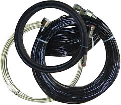
The hydraulic hose assembly is an assembly structure formed by crimping and assembling the two ends of the hose reinforced by steel wire braiding or winding and the metal connecting joints. The hydraulic hose assembly is an important part of the hydraulic system. When we choose hydraulic pipes, we must understand the requirements of their use environment and related parameters, as well as the model identification method of hydraulic pipes.
1. Composition of hose assembly
A hose assembly usually consists of three parts: hose, connector (2 pieces) and clamp or sleeve (when necessary). The connector and sleeve are usually designed with barbs and other structures in the part in contact with the hose to achieve good friction between the connector and the hose and ensure that the connector can withstand sufficient end force during use.
The connection forms of metal connectors are divided into threaded and flange types. Common sealing types of threaded connectors include 24° cone O-ring elastic seal, 74° cone metal hard seal, and flat O-ring elastic seal.
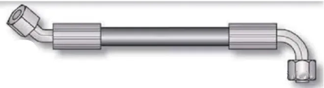
The schematic diagram of the structure of the hydraulic hose assembly after crimping and assembly is as follows:
2. Hose assembly length and assembly angle
(1) Hose assembly length
The hose assembly length is the horizontal distance measured based on the end faces of the two hose connectors or the center of the elbow connector. The length of the hose assembly allows a manufacturing error of ±1%. A hose that is too long affects the appearance and increases costs. If it is too short, when the hose is stretched or compressed under pressure, there is not enough room for expansion and contraction, which can also cause the hose to be damaged.
(2) Hose assembly angle
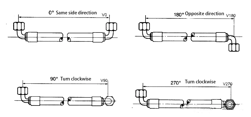
The concept of assembly angle exists only when there are hose assemblies with elbows at both ends. In this case, the assembly angle is defined as follows:
Place the hose assembly on the same straight line, take the vertical direction of an elbow at the far end as the reference, and measure the angle between the other elbow and the far end elbow (vertical direction) in a clockwise direction. This angle is the assembly angle. The allowable error of the assembly angle is ±3°.
The four commonly used angles are shown in the figure below:
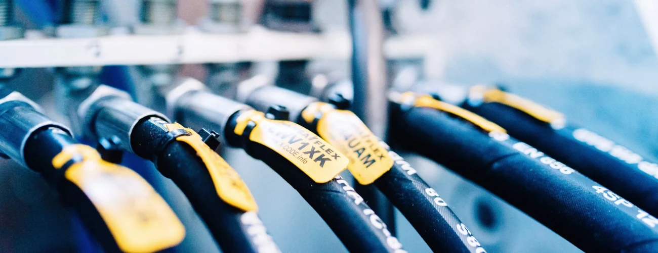
3. Hose assembly identification method
The model identification method of hydraulic hoses is usually represented by a code consisting of numbers and letters, including the following parameters:
(1) Inner diameter: The diameter of the inner layer of the hose, generally in mm. The larger the inner diameter, the stronger the pressure-bearing capacity of the hose.
(2) Wire diameter: The diameter of the steel wire or fiber used in the reinforcement layer, in mm. The larger the wire diameter, the stronger the pressure-bearing capacity of the hose.
(3) Length: The entire length of the hose, in mm.
(4) Pressure: The maximum pressure that the hose can withstand, usually expressed in bar. The greater the pressure, the stronger the pressure-bearing capacity of the hose.
In actual applications, the model identification method of hydraulic hoses may also include other special parameters, such as temperature range, bending radius, etc. Different combinations of these parameters can meet different usage requirements. The hose assembly is generally marked with the following information:
(1) Hose type, including basic information such as hose structure and inner diameter.
(2) Left end connector type, including connector structure and thread specifications.
(3) Right end connector type, including connector structure and thread specifications.
(4) Length, which is the straight length of the hose, in mm.
(5) Supplementary information, such as assembly angle, sheath, etc.
(6) Other information, such as special properties such as high temperature resistance and corrosion resistance, represented by letters or numbers.
4. Hose assembly model marking example
For example, Parker’s hydraulic hose model: F381CFCF282812-1800-270°, where:
F——indicates that the hose is crimped;
381——series number, representing the series type of the hose, with a pressure range of 88-400bar, universal 2-layer steel wire braiding, and a temperature range of -40°C to +100°C;
CFCF——external connection form of the left and right joints;
282812——the outer diameter of the steel pipe at the outer connection end of the left and right CF joints is 28mm, and the internal connection specification of the hose is 12mm;
1800——hose assembly length;
270°——the assembly angle at both ends of the hose is 270 degrees.
The hydraulic hose model can be marked differently by different manufacturers. It is recommended to refer to the product description or contact the seller or manufacturer for accurate information.