News
Commonly asked questions about single-turn and multi-turn angle encoders
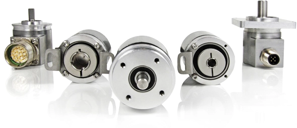
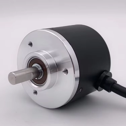
Angle encoders are important sensors in industry that provide feedback on mechanical position angle, length, and speed and participate in control. Angle encoders are divided into incremental encoders, absolute encoders, and absolute multi-turn encoders..
1. Can the encoder be used with PLC?
It can be used as long as there is a corresponding communication interface on the PLC.
2. What is the difference between single turn and multi-turn?
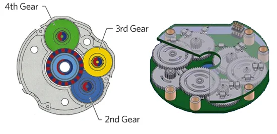
In single turn, the value will restart from 0 after more than 1 turn (single turn can also be used as electronic multi-turn, and can be counted multiple times after power failure); in multi-turn, for example 24 turns, the number of turns within 24 turns will be memorized after power failure, and the count will restart from 0 after more than 24 turns. The encoder uses mechanical gears (similar to the structure of a clock) to memorize the number of turns, and the data will not be lost after power failure.
3. What does the midpoint of the encoder mean?
The midpoint refers to the voltage (current) at the zero position. If you customize the output of 0-5V (4-20mA), the zero position is 2.5V (12mA).
4. What is an absolute encoder and what are its advantages?
The definition of “absolute value” inside an absolute encoder refers to all position values inside the encoder. After the encoder is manufactured, all positions within its range have been “absolutely” determined in the encoder. After the origin is initialized, each position is independent and unique. Each internal and external data refresh reading does not depend on the previous data reading. Whether inside or outside the encoder, there should be no “count” and the accumulation of previous readings, because such data is not “independent”, “unique”, “all positions within the range have been absolutely established in advance”, and it does not meet the meaning of the word “absolute”. Therefore, the definition of a true absolute encoder refers to the absolute correspondence between all positions within the range and the origin position in advance, which is independent and unique absolute encoding that does not depend on internal and external count accumulation.
5. What are the disadvantages of incremental encoders?
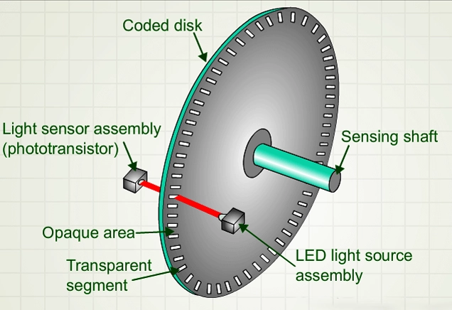
From the perspective of external receiving devices (such as servo controllers and PLCs), incremental values refer to a relative change in position information, the calculation of the increase and decrease of the signal from point A to point B, also known as “relative value”. It requires uninterrupted counting by subsequent devices. Since each data is not independent but depends on the previous reading, the error caused by power outages and interference in the previous data cannot be judged, resulting in accumulated errors.
6. What issues should be paid attention to when using high-precision encoders?
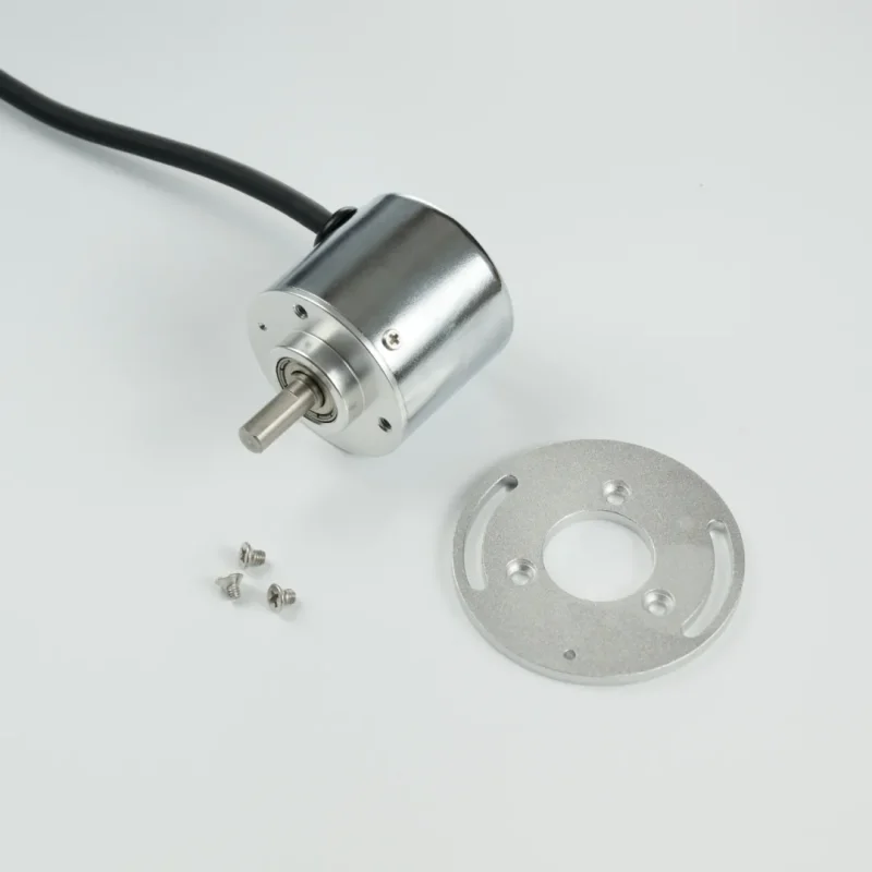
High-precision encoders are devices that convert changes in mechanical angle physical quantities into electrical signals. Encoders are mainly used to measure the angular displacement, angular velocity, and angular acceleration of rotating objects. High-precision encoders can convert these physical quantities into electrical signals and output them to the control system or instrument. The control instrument controls the drive device based on these quantities.
(1) Electrical aspects
① Please do not entangle the output line of the high-precision encoder with the power line, and do not place it near the distribution board to prevent interference. Shielded cables should be used for wiring. The transmission distance of the pulse signal is related to the following factors: frequency, output circuit, input circuit, transmission line, and transmission frequency.
② Before installation and startup, carefully check whether the product manual matches the encoder model and whether the wiring is correct. Incorrect wiring will cause damage to the internal circuit. When transmitting over long distances, signal attenuation factors should be considered, and an output method with low output impedance and strong anti-interference ability should be selected.
(2) Mechanical aspects
① The connection between the high-precision encoder and the user’s output shaft should use an elastic soft connection to reduce the damage to the encoder shaft system and code disk caused by the string movement and jump of the user’s shaft. Do not hit the encoder with a hammer when installing it. Pay attention to the allowable shaft load during installation and do not exceed the load.
② The different speeds of the encoder shaft and the user’s output shaft should be <0.2mm, and the deviation angle with the axis should be <2°. Be careful not to exceed its electrical limit speed. If the speed exceeds the limit speed allowed by the encoder, the wire signal will be lost.
(3) Environmental aspects
① Because the high-precision encoder is a precision instrument, do not splash water, oil, etc., and do not have interference sources. Pay attention to whether the ambient temperature and humidity are within the range required for the instrument.